How ultra-wideband works
This article is part of the Pozyx Academy and is the second in a series of five articles that explain how the Pozyx Technology works and what to account for when installing the Pozyx System.
- How positioning works
- How ultra-wideband works
- Positioning protocols explained
- Ultra-wideband and obstacles
- Where to place the anchors
Traveling at the speed of light
The previous Pozyx Academy article, ‘How positioning works’, explained how to obtain a position by measuring the distance to reference points. Ultra-wideband technology works differently and measures how long it takes for a radio wave to get from the asset to the anchor or reference point. This is called time of flight (TOF).
Because radio waves travel at the speed of light, the time of flight is measured by this speed to get the distance. The speed of light is fast. In a single nanosecond, which is a billionth of a second, a wave has traveled almost 30 cm. This means the timing has to be measured very accurately to perform centimeter-accurate ranging.
It's all about the bandwidth
Heisenberg’s uncertainty principle states that it is impossible to know both the frequency and the timing of a signal. Consider for example a sinusoid; a signal with a well-known frequency but a very ill-determined timing: the signal has no beginning or end. However, multiple sinusoidal signals with a slightly different frequency combined create a pulse with a more defined timing, i.e. the peak of the pulse. This is seen in the following figure from Wikipedia that sequentially adds sinusoids to a signal to get a sharper pulse:
The range of frequencies that are used for this signal is called the bandwidth Δf. Using Heisenberg's uncertainty principle the width Δt of the pulse can be determined, given a certain bandwidth Δf*:
ΔfΔt ≥ 1/4π
This formula shows that a large bandwidth is needed to create a narrow pulse, which is necessary for accurate timing. For example, using the bandwith of Δf = 20 MHz (available for wifi systems), a pulse width larger than Δt ≥ 4ns is obtained. the speed of light, this relates to a pulse of 1.2 m 'long' which is too much for accurate ranging. We can conclude that wifi systems are inaccurate for accurate positioning, firstly, because it is hard to accurately determine the peak of such a wide pulse, and secondly because of reflections.
Reflections are signals that bounce onto objects (walls, ceilings, desks, etc..) within the surrounding environment. These reflections are captured by the receiver and may overlap with the line-of-sight pulse which makes it hard to measure the true peak of the pulse. With pulses of 4 ns wide, any object within 1.2 m of the receiver or the transmitter will cause an overlapping pulse. Because of this, ranging from wifi using time-of-flight is not suitable for indoor applications.
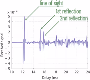
The ultra-wideband signals that are used in the Pozyx System have a bandwidth of 500 MHz resulting in pulses of 0.16 ns wide. This timing resolution is so fine that at the receiver, we can distinguish several reflections of the signal. Hence, it remains possible to do accurate ranging even in places with a lot of reflectors, such as indoor environments.
Where to find bandwidth
In conclusion, precise positioning via UWB requires 500 MHz of bandwidth, which is a lot. Unfortunately, everybody wants a lot of bandwidth, because in wireless communication systems, more bandwidth means faster downloads. However, if everybody would transmit signals on the same frequency, all the signals would interfere and nobody would be able to receive anything meaningful. Because of this, the use of the frequency spectrum is highly regulated.
So how is it possible that UWB gets 500 MHz of bandwidth and most other systems have to be satisfied with a lot less? Well, the UWB systems are only allowed to transmit at very low power (the power spectrum density must be below -41.3 dBm/MHz). This very strict power constraint means that a single pulse does not reach far: at the receiver, the pulse will likely be below the noise level. In order to solve this issue, a train of pulses is sent by the transmitter (typically 128 of 1024) to represent a single bit of information. the received pulses are then accumulated at the receiver and with enough pulses, the power of the 'accumulated pulse' will rise above the noise level and reception is possible.
The IEEE 802.15.4 standard for Low-Rate Wireless Personal Area Networks has defined a number of UWB channels of at least 500MHz wide. Depending on the country, certain channels are allowed. The lower band channels (1 to 4) can be used in most countries under some limitations on update rate (using mitigation techniques). Channel 5 is accepted in most parts of the world without any limitations, with the notable exception of Japan. Purely from physics, the lower the channel center frequency, the better the range.
A note on the received signal strength (RSS)
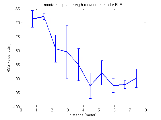
Received signal strength (RSS) is another way to measure the the distance between two points by using radio waves. The further the two points are, the smaller the received signal strength will be. Hence, from this RSS-value, we should be able to derive the distance. It is however not that simple. The received signal strength will be a combination of the power of all the reflections and not only of the desired line-of-sight. Because of this, it becomes difficult to relate the RSS value to the true distance, as becomes clear from the image below.
In this figure, the RSS value of a Bluetooth signal is measured at certain distances. At every distance, the error bars show how the RSS value behaves at the given distance. Clearly, the variation on the RSS value is very large which makes RSS unsuitable for accurate ranging or positioning.
Read the next article on positioning protocols to learn more about Pozyx’s technology.